CORE EQUIPMENTS
| Drive Module |
Rear-Axle Powertrain With The Gearbox, 15 Kw Asynchronous Motor, A Control Unit With Controller &DC/DC Converter, |
| E-Car-Box |
Air-Cooled Curtis Controller, Contactor, A DC/DC Converter And All Necessary High- And Low-Voltage Fuses. |
| Battery Management System (BMS) |
System Monitors The Lithium Iron Phosphate Battery Cells |
ELECTRIC VEHICLE SYSTEM
INDIAN SECENERIO
Electric vehicles could be a better alternative to IC engine of fuel engine vehicles to reduce air pollution, but the government's aim is to replace all Fuel Vehicle to electric vehicles in the next decade, that clearly indicates that by 2030 goverment is aiming to make india 100% Electric Vehicle Country.In India, a particular set of circumstances which are conducive to a sustainablemobility paradigm have created an opportunity for accelerated adoption of EVs over ICE vehicles.
Such as
- A relative abundance of exploitable renewable energy resources.
- High availability of skilled manpower and technology in manufacturing and IT software.
- An infrastructure and consumer transition that affords opportunities to apply technologiesto leapfrog stages of development.
- A universal culture that accepts and promotes sharing of assets and resources for theoverall common good.
DETAILS OF EQUIPMENT
DESCRIPTION:
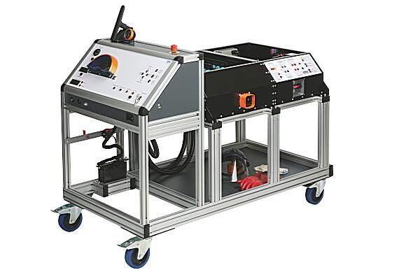
The functional model for electric drives and HV systems in vehicles consists of a drive module and an energy supply and control module. The HV system works with an operating voltage of 96 V. It includes a complete energy supply unit with an electronic battery management system (BMS), an integrated charger for the HV battery, a control unit with an engine management system, all of the necessary safety components, a Mennekes charging connection and an extra robust service disconnect. The HV battery, with a nominal voltage of 96 V, is equipped with 32 LiFePO4/40 Ah cells. The battery management system features a Bluetooth interface. A corresponding app (Android) can be used to display the condition (voltage, temperature, balancing rate during the charging process) of each individual battery cell.
MAJOR EQUIPMENTS DETAILS:
The system comprises of three systems Drive Module, E-Car-Box & Battery Management System.
1.Drive module
The drive module consists of a complete rear-axle powertrain with the gearbox from the Smart 450, 15 kW asynchronous motor, a control unit with controller (E-Car-Box), DC/DC converter, fuses, contactors and control software, and a hydraulic brake for load simulation (uphill driving).
2.E-Car-Box
The E-Car-Box is the core element of the drive. It houses all key components for actuating the motor in a space-saving, secure and EMC-compliant manner; these are cabled in accordance with the most stringent safety standards. In addition to the air-cooled Curtis controller for actuating the motor, it also contains the main contactor, a DC/DC converter and all necessary high- and low-voltage fuses.
3.Battery management system (BMS)
The battery management system monitors the lithium iron phosphate battery cells installed in the HV trainer and the extent to which they are protected against overvoltage and under voltage during the charging process and while driving. As such, the central control unit communicates with the connected charger and motor controller via CAN interface. The battery management system features a Bluetooth module for communication between the BMS and a display instrument such as a smartphone, tablet or Bluetooth-compatible Windows PC. Apps for Windows Mobile and Android are available for download. This module enables the state of charge of the batteries and various other parameters to be monitored.
LEARNING TARGETS:
- Observing accident prevention regulations
- Avoiding dangers when working with electrical current and hazardous substances
- Selecting suitable and safe testing and measuring instruments
- Handling and using safety equipment
- Applying manufacturer-specific test routines
- Disconnecting high-voltage components, securing them against being switched back on, disconnecting from the voltage supply
- Identifying the dangers of electric storage (capacitors, high-voltage batteries)
- Identifying the general principles of electrical engineering
- Creating system and block diagrams
- Identifying electrical variables and their effect on the human organism
- Troubleshooting and interpreting the diagnostics of affected systems
- Analyzing the function and interaction of components, taking into account the exchange of information between participating control units
- Identifying system relationships using circuit diagrams and function plans
- Analyzing time-dependent variables and evaluating signal patterns
- Applying knowledge of the principles of voltage generation (induction), rectification (half-wave and full-wave rectification), the electromotive principle and storing electrical energy
- Assessing hazards when performing live measurements, deriving protective measures and testing the effectiveness of the electronic protective measures of the high-voltage system
- Performing live measurements (insulation, potential equalization and voltage drop measurements, battery cell voltages, temperature measurement)
- Performing function testing on high-voltage systems (actuation signals of the electric motor while driving)
- Assessing measured values and signals for plausibility and creating test records
- Planning the diagnostics and repair of the high-voltage system and its components
FUNCTIONS CAN BE PERFORMED:
- Disconnect from the voltage supply with service disconnect
- Ascertain disconnection from the voltage
- Secure against switching on again
- Measure the intermediate circuit capacitor charge and discharge curve
- Localise defective battery cells using measurement technology
- Replace battery modules
- Check the connector between the cells for contact resistance
- Perform function testing on the contactors
- Check the safety line (interlock circuit)
- Check the insulation monitor
- Check the motor encoder and motor temperature sensor
- Clearly present the load simulation (uphill driving) visually and in such a way that it can be measured
- Program the HV controller with manual programmer or PC interface
SUITABLE FOR:
- Mechanical Engineer
- Electrical Engineer
- Electronics Engineer
- Automobile Enthusiasts.