MECHATRONICS AND INDUSTRY 4.0 LAB
CORE EQUIPMENTS
| MECHATRONICS SYSTEMS |
5-Station-Automated Product Assembly system- Christiani, Germany.
3-Station- Automated Product manufacturing system- R & D Development. |
| SENSORICS |
Industry 4.0 (Smart Sensors) , Sensorik Kit, Identification System- Pepperl+Fuchs |
| AXIS MANUPULATOR |
A Collaborative Robot Arm By ST-Robotics. |
 Mechatronics System with SIMATIC S7-314C-2PN/DP - Fully Assembled & Programmed
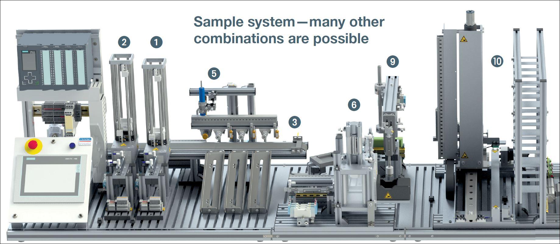
The Mechatronics System SSC2P2HV2 offers a complete production process with material sorting and is delivered fully assembled, wired, programmed and tested. It is ideally suitable for teaching PLC programming and visualization, as well as for commissioning and troubleshooting of automated industrial Mechatronics systems. For these applications the SSC2P2HV2 offers a safe environment for students to explore modern industrial automation.
The project documents assist you and your students when working with the system and provide all relevant information for self-contained learning and action-based training.
DETAILS
PROCESS DESCRIPTION:
After separation of work pieces (cube halves) from the Magazine Units to the Belt Conveyor their material properties and orientation are determined. Subsequently work pieces can be sorted onto three slides or moved forward to the end of the Belt Conveyor. There the cube halves are picked up by a Handling Unit and moved to the Pneumatic Press. In the Press Unit both cube halves are joined together. Subsequently the Handling unit again fetches the manufactured cube and forwards it to the ASRS where the cube is stored by the rack feeder.
The system uses work pieces made of aluminum, white and black plastic and spring pins for joining the cube halves.
SYSTEM DESCRIPTION:
The Mechatronics system consists of 3 base plates (T-slotted AL-profile plates) which are equipped with the following Mechatronics functional units:
2 Pneumatic Service Units, 2 Magazine Units, Belt Conveyor, Sorting Unit (for material testing and sorting), Handling Unit with vacuum suction, Pneumatic Press, ASRS with rack feeder. The Mechatronics system is controlled by two SIMATIC S7-1516-3 PN/DP programmable logic controllers (PLC) and two SIMATIC TP700 Comfort HMI color touch panels. Both PLCs are connected via ProfiNet. The ProfiBus interface on board the PLCs may be alternatively used to teach and evaluate ProfiBus communication instead ProfiNet.
With little effort the system can be separated mechanically and electrically in two segments. Both controls work independently and each control takes care only of the connected system part.
Detailed information regarding the used and above mentioned functional units are available on our web sites.The Mechatronics system is provided fully assembled, programmed, tested and ready to use.
The PLC program is written in SIMATIC STEP 7. All comments within the PLC program are in English, as well as the documentation belonging to the complete system.
LEARNING TARGETS:
- Operative and technical communication
- Sensor types and sensor application
- Actuators in Mechatronics systems
- Pneumatics
- Measurement and testing of electrical signals
- Testing and adjusting sensors and actuators in Mechatronics systems
- Commissioning and operation of Mechatronics systems
- Troubleshooting and servicing of Mechatronics systems
- Programming automated industrial systems
- PLC programming
- Networking via ProfiNet with interlinked PLCs
- Design and programming of graphical user interfaces (HMI)
TECHNICAL DATA:
Primary power supply: 230 VAC, 50 Hz
Internal voltage level: 24 V DC
Required air supply: min. 6 bar, max 10 bar
Average air consumption: approx. 10 l/min
Dimensions (LxBxH): 2000 x 550 x 650 mm (height without trolleys)
Mass: ca. 120 kg (unpacked, without trolleys)
For system operation a suitable air supply is required.
 Mechatronics System with SIMATIC S7-1512C-1PN – Automated Product Manufacturing System
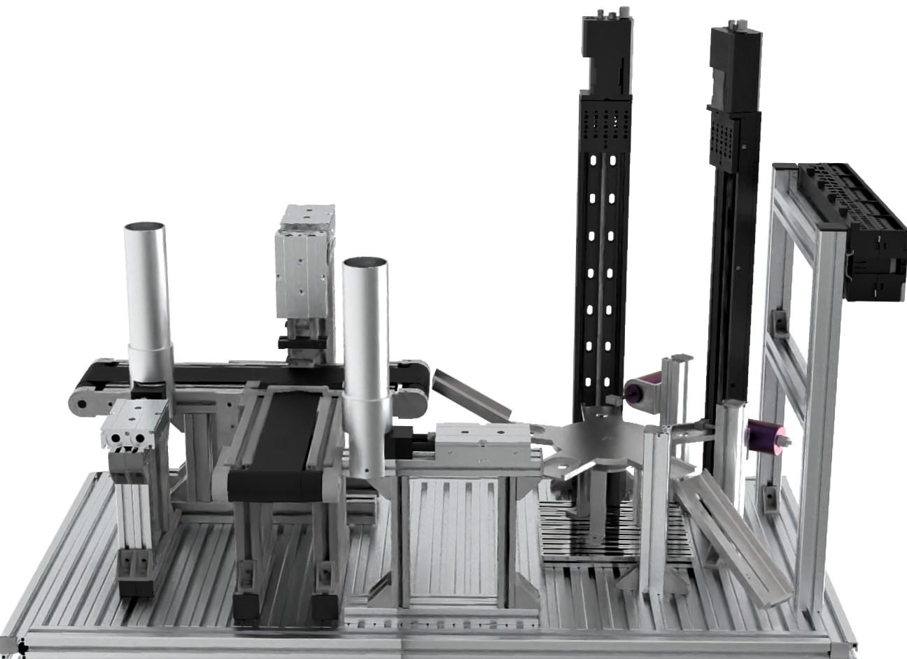
The Mechatronics Automation Station aims at working without human efforts in which different machining operations like drilling; reaming is performed on jobs or workpieces with its quality checking or inspection. In this station, workpieces move from magazine to rotary indexing table with the help of conveyor, and then workpieces are assembled and processed on a rotary indexing table. This station only uses electrical drives. The rotary indexing table is driven by a Stepper motor. The rotary table is positioned by an inductive sensor. On the rotary indexing table, the workpieces are tested and drilled in two parallel processes. During drilling and reaming the workpiece is clamped by a solenoid actuator. A computer vision is used to check the dimension of the workpiece.
DETAILS
PROCESS DESCRIPTION:
| Stations |
Functions |
| Distribution |
Separate out a work piece from the magazine. Make the work piece available for a subsequent process on conveyor. |
| Assembly |
Assembly of two parts with the help of pick and place unit |
|
Processing
|
Consist of various operations such as Drilling, Reaming and Computer vision.
|
| Checking |
Computer Vision inspects the dimension of the workpiece. |
| Rejection & Acceptanc |
Removes the rejected parts from the processing station.Accepted workpieces are stored in pallets. |
SYSTEM DESCRIPTION:
Belt conveyor: is an equipment to move materials/objects from one end to other between its extreme ends. This is a miniature model of a real time industrial conveyor system. The operation of the conveyor is limited to single direction according to the usage. The conveyor belt rolls over two pulleys fixed on either end.
Mechatronics Pneumatic Kit: has the capability to control solenoid valves, different cylinders, different control valves, sensors, etc. Pneumatic kit is used to control and actuate the various movements of the Linear single/Double acting cylinders, adding feasibility to the sense of the position of the cylinder with the help of different types of sensors; one for Inductive and other for Non-inductive applications, controlling various types of solenoid valves, regulators, etc. for pneumatic automation applications.
Rotary Table: specifically designed to rotate at fix angular displacement and integrated motion system is controlled by stepper motor.
Camera is connected to the raspberrypi controller where processing mainly involves image processing and vision-based algorithms and outputs typically are the analysis of the captured images and decision-making parameters
The Mechatronics system is controlled by two SIMATIC S7-1516-3 PN/DP programmable logic controllers (PLC) and two SIMATIC TP900 Comfort HMI color touch panel’s .Both PLCs are connected via ProfiNet. The ProfiBus interface on board the PLCs may be alternatively used to teach and evaluate ProfiBus communication instead ProfiNet.
With little effort the system can be separated mechanically and electrically in two segments. Both controls work independently and each control takes care only of the connected system part.
LEARNING TARGETS:
- Operative and technical communication
- Sensor types and sensor application
- Actuators in Mechatronics systems
- Pneumatics
- Computer Vision
- Testing and adjusting sensors and actuators in Mechatronics systems
- Commissioning and operation of Mechatronics systems
- Troubleshooting and servicing of Mechatronics systems
- Programming automated industrial systems
- PLC programming
- Networking via ProfiNet with interlinked PLCs
- Design and programming of graphical user interfaces (HMI)
TECHNICAL DATA:
Primary power supply: 230 VAC, 50 Hz
Internal voltage level: 24 V DC
Required air supply: min. 6 bar, max 10 bar
Average air consumption: approx. 10 l/min
Dimensions (LxBxH): 1000x500x400 mm (height without trolleys)
Mass: ca. 30 kg (unpacked, without trolleys)
For system operation a suitable air supply is required.
ASSEMBLY UNIT
FUNCTIONAL UNIT: ASSEMBLY UNIT:
The assembly unit is designed for assembling or attaching work pieces. After inserting the work pieces, the workpeice holder transports the parts to be processed to the workspace. Then, the safety door closes, and the joining cylinder begins extending. After the assembly of the cube halves, the safety door opens. The joint work pieces are pushed out of the workspace and are ready for further transport.
Due to the safety door, the Assembly Unit is fully enclosed workspace during processing. However, the safety walls made of plexiglass make it possible to observe the joining procedure.
The operating pressure is 4 bar. The operating voltage is 24 VDC.
DESCRIPTION:
- Work plan, technical communication
- Testing, marking and identification
- Manual and mechanical machining, separating and reshaping
- Assembly work, joining
- Design of electrical control systems
- PLC programming
- Commissioning of mechanical, electrical and pneumatic systems
- Troubleshooting
- Automation of work processes
- Design and function of electro-pneumatic systems
5-AXIS COLLABORATIVE ROBOT
 5-Axis Collaborative Robot Arm By St Robotics
FEATURES:
5-Axis Collaborative Robot Arm By St Robotics
FEATURES:
- 500 mm reach 5-axis articulated format, optional 6th axis.
- Collaborative robot (Cobot). Optional safety system.
- Easy mounting of tools, grippers, sensors etc.
- Fully enclosed; pneumatics and wiring go through the arm, not strapped to the outside.
- Optional tool changer and mountings for tools.
- User friendly interactive software, English language commands.
- Input/output interfacing, optional I/O expansion.
- Non-volatile memory, turnkey option.
- Complete with controller, software, on-screen manuals, cables, etc. Ready to go.
- Optional pneumatic or electric grippers, vacuum pickup, tool changers.
- Supplied ready to run-robot, controller, all cables, Windows GUI project manager, teach pad.
- Running within 10 minutes of taking it out of the box.
- Optional linear track.
- Free simple intuitive teach pad, optional Android Bluetooth console.
- Optional control over TCP/IP, voice control.
- Outstanding reliability, zero scheduled maintenance.
- Support for ROS, LabView, Matlab etc.
DETAILS
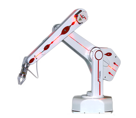
The R12 is a complete self-contained five or six axis vertically articulated robot arm system designed as a cost effective solution for bench top automation. Applications include testing, sample handling, machine feeding. The hand terminates in a mounting plate to which can be mounted one of our low cost grippers, vacuum pickups or your own device.
R12 is a very low cost entry to real industrial robotics, fast, accurate and reliable and easy to program yet capable of the most complex tasks. It has a useful 500mm reach and a 500g payload. Designed by a young engineer building on our existing R17 technology it is a breakthrough in bench top robotics. It is lighter, faster and quieter than R17, using high efficiency digital motors driving through steel reinforced polyurethane timing belts. Optional incremental optical encoders provide exceptional integrity as well as safety (see below).
Note that R12 is not a hobby robot. It is a professional tool made to industrial standards, machined from solid alloy and finished with aesthetic acrylic covers.
The system is supplied complete with controller, all cables, connectors, software, comprehensive manuals, ready to unpack and use immediately.
The R12 package includes the K11 controller that is simple and reliable using a partnership of CPU and DSP micro-processors and compact micro-stepping drives. ROBOFORTH II embedded software gets you started easily yet permits the most complex motions, interfaces and peripherals to be programmed, assisted by ROBWIN project manager that brings everything together on one Windows screen.
SPECIFICATIONS, 5-AXIS VERSION
| Drives: |
High power micro-stepped hybrid stepping motors, optional encoder watchdogs |
| Reach: |
500mm/20ins in any direction; 360 degree waist rotation |
| Repeatability: |
0.1mm (see note) |
| Payload: |
nominal 500g, max 1Kg (2.2lbs) at flange(repeatability and speed degrade with increasing payload and reach). |
| Compliance: droop at 250mm at nominal payload: |
0.4mm |
| droop at max reach with max payload: |
2.3mm |
| Maximum speed: |
Waist 220 deg/sec, Shoulder 200 deg/sec, Elbow 500deg/sec, hand 600deg/sec, wrist roll 600 deg/sec. Max linear speed approx 800mm/s. Standard Cycle 2s |
| Max torque for pitch or roll: |
1 Nm (repeatability figures degrade with increasing load). |
| Weight |
Robot 12.8Kg/28lbs Controller 11kg/25lbs |
| Power: |
110/240v ac 420VA (standard controller) |
| Environment: |
IP 54A, 0 - 40C (wider range optional) |
| MTBF: |
15,000 hours (typically over a million cycles) |
| Safety: |
Class 2 stop circuit, stall detect, risk assessment guide.
Optional LED awareness barrier, optional workspace sentry system. |
| Noise: |
Approx 40-50dB at 1m. |