CORE EQUIPMENTS and SOFTWARES
| YASKAWA AR1440 Welding Robot with YRC 1000 Controller. |
| MotoSim EG-VRC |
| TATA TAL BRABO Robot |
MOTOMAN AR1440
The six-axis MOTOMAN AR1440 robot provides fast and accurate performance to achieve optimal results in extremely difficult conditions and especially for the high demands of arc welding applications. With a payload of up to 12 kg, it’s wire feed system, the maximum working range of 1440 mm and integrated media hose package, this robot enables simple machining of bulky and hard-to-access workpieces with high quality results. Furthermore, the slim design allows high-density robot placement in confined spaces. The fast motion sequences of the MOTOMAN AR1440 robot reduce welding cycle times and the hollow wrist of 50 mm allow integrated torch cabling in the robot arm in order to avoid collisions with the workpiece or other robots. The integration of the power cable and the air connections in the base enable an enlarged turning range of more than 340°.
SPECIFICATION
| Axes |
Maximum motion range (°) |
Maximum speed (°/sec) |
Allowable moment (N*m) |
Allowable moment of inertia (kgm²) |
| S |
± 170 |
260 |
* |
* |
| L |
+155/-90 |
230 |
* |
* |
| U |
±140 |
260 |
* |
* |
| R |
±150 |
470 |
22 |
0.65 |
| B |
+90/-135 |
470 |
22 |
0.65 |
| T |
±210 |
700 |
9.8 |
0.17 |
SPECIFICATION
| Item | AR1440 |
| Controlled axes | 6 |
| Maximum Payload (kg) | 12 |
| Repeatability (mm) | ±0.06 |
| Horizontal Reach (mm) | 1440 |
| Vertical Reach (mm) | 2511 |
| Weight (kg) | 150 |
| Internal user I/O cable | 17 conducts w/ ground |
| Internal user air line | 3/8 connection |
| Power Requirements | 380-480 VAC |
| Power rating (kVA) | 1.5 |
KEY BENEFITS
- Fast motion sequences
- Wide motion range
- High path accuracy
- High density placement due to slim design
- Integrated cabling avoids interferences
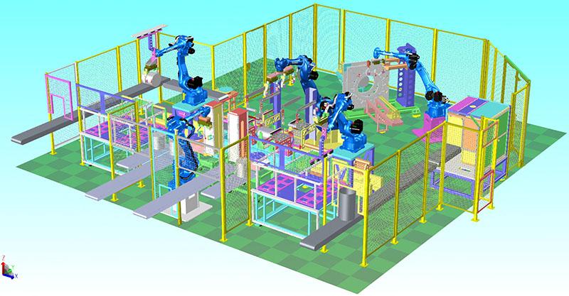
Build and Simulate a Robotic Work cell
Offline programming, 3D simulation and Virtual Robot Control all make it easy to build and simulate a robotic cell without ever installing a robot. Yaskawa provides MotoSim EG and MotoSim EG-VRC for building and simulating your robot cell. In addition, if you need to ensure you select the proper robot based upon load ratings and payload, let MotoSim determine the proper robot model.
MOTOSIM EG-VRC
MotoSim EG-VRC (Enhanced Graphics Virtual Robot Controller) is designed for accurate offline programming of complex systems. With the virtual robot controller function, simulation software can be used for
- Optimizing robot and equipment placement
- Reach modeling
- Accurate cycle calculations
- Automatic path generation
- Collision detection
- System configuration
- Condition file editing
- Functional Safety Unit (FSU) configuration
- Remote access to real robot controller
The virtualized controller also allows the simulation software to operate and display a programming pendant interface identical to the real controller. The VRC completely simulates the Motoman robot controller software.
MOTOSIM EG
MotoSim EG (Motoman Simulator Enhanced Graphics) is a comprehensive software package that provides accurate 3D simulation of robot cells. This powerful simulation software can be used to optimize robot and equipment placement, as well as to perform collision detection, reach modeling and cycle calculations. It also provides accurate offline programming of complex systems.
MotoSim EG reduces programming time, thus increasing uptime of the production equipment. New parts can be programmed offline before production begins, and existing robot programs can be modified to increase efficiency and reduce cycle time – without sacrificing production schedules.
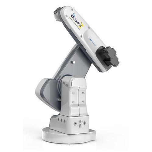
TATA TAL BRABO
India’s first articulated industrial robot “BRABO” has been unveiled by Tata Motors’ wholly owned subsidiary, TAL Manufacturing Solutions. Bravo Robot or BRABO is country’s first conceptualized, designed and manufactured articulated industrial robot that has been specially developed for nation’s micro, small & medium enterprises.
The articulated industrial robot has been developed by TAL with an aim to recurrently perform time-consuming, high volume, and dangerous tasks that range from raw material handling to finished-product packaging. The main purpose of developing BRABO is to complement human work force.
SPECIFICATION OF TATA TAL BRABO
| Parameter |
Value |
| Robot make |
TAL BRABO |
| Robot model |
TR10-5 |
| Construction |
Articulated arm |
| Ambient temperature of the robot workspace |
0° C to 45° C |
| Relative humidity of the robot workspace |
Less than 90% |
| Number of Axes |
5 |
| Axis movement range |
J1- AXIS: ±180°
J2-AXIS: ±130°
J3-AXIS: ±150°
J4-AXIS: ±180°
J5-AXIS: 360° |
| Maximum speed |
J1- AXIS: 110°/s
J2-AXIS: 110°/s
J3-AXIS: 110°/s
J4-AXIS: 150°/s
J5-AXIS: 150°/S
|
| Maximum Payload |
10Kg |
| Maximum reach (horizontal) |
750mm |
| Weight of robotic arm |
95Kg |
| Position repeatability (accuracy) |
±0.2 mm |
| Main power supply |
230V AC, Single phase, Regulated power supply |
| Full load current |
15 Amps |
| Maximum power consumption |
4.5KW |
| Acoustic level |
Less than 70 db |
| Robot controller dimensions |
660 * 660 * 350mm |
| Robot controller weight |
45 Kg |
| Spare digital I/O |
3 Input, 4 output (Bidirectional) |
| Communication protocol |
Ethernet, Ether CAT |